Lesson
6: Fiber Optic Testing
Objectives:
From this lesson you should learn:
What needs testing in fiber optics
How to trace fibers and locate faults with a visual fault
locator
How to inspect and clean fiber optic connectors
How to measure optical power
How to measure insertion loss with a light source and
power meter
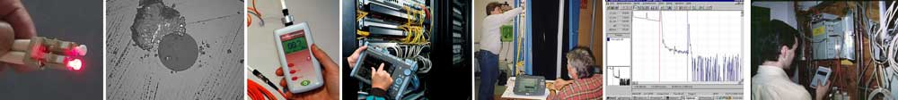
Testing
cable plants and patchcords
3 Methods of
setting a "0dB" reference
Factors
affecting measurement uncertainty
How to use an
OTDR properly
Setting up OTDR test parameters
Interpreting
OTDR traces
Factors
affecting OTDR measurement uncertainty
Tools
And Components Needed
Visual
Fault Locator
Fiber optic inspection microscope with adapters
for connectors being inspected - typically 2.5mm
ferrule (SC/ST/FC) and 1.25mm ferrule (LC)
Fiber optic power meter with
adapters for connectors being inspected
Fiber optic light source appropriate for fiber and
cables being tested (850/1300nm LEDs for MM,
1310/1550nm laser for SM)
Jumper cables for use as reference test cables appropriate
for fiber and cables being tested (2+m
long preferred)
OTDR appropriate
for fiber and cables being
tested (850/1300nm for MM,
1310/1550nm laser for SM)
Launch and receive cables for OTDR testing
(typically >100m, depending on the OTDR
resolution and preferably from the same fiber)
Consult the Workbook
section on Testing for equipment needed
or refer to the CFOT
Certification Lab Manual
Introduction
Fiber
optic testing is the least well understood aspect of fiber
optic installation. That's what manufacturers say and
exactly what we see on FOA certification exams. Granted
fiber optic testing is not simple (mostly because of the
complexity of the instruments) but it is straightforward.
The principles are easily learned and if applied in
everyday use, they become habits for the competent
installer.
Recognizing the complexity of fiber optic testing, the FOA
devotes a chapter (Chapter 8) in our basic fiber and OSP
textbooks and has created a complete textbook on fiber
optic testing that expands on every subject in testing and
covers some advanced topics that are not in our basic
textbooks. If you are doing fiber optic testing, we highly
recommend you get a copy of this book for reference. FOA
Reference Guide To Fiber Optic Testing.
This lesson covers the basic fiber optic tests used to
test components and installed cable plants. It includes
six separate exercises that will each take some time to
complete.
Make certain
before you begin each exercise that you have everything
you need - tools, test equipment and components. Refer to
the check list on Lesson 2.
Safety
 |
Please
Note: This is not the usual online
course - it is intended to guide you as
you learn new skills - the "hands-on"
skills needed to install optical fiber
cable plants. It involves using tools
and components in a realistic manner.
Some of the processes here can be
hazardous, like working with sharp
scraps of optical fiber and chemicals.
In
Lesson 1 you should have familiarized yourself
with the safety procedures - follow them all
the time. Do not work with fiber without eye
protection and a proper work area that is easy
to clean up.
Always wear safety glasses when doing
any of these exercises and dispose of
all scraps properly. |
Follow the safety procedures learned in lesson 1 with some
special warnings for testing. Do not use a microscope to
inspect connectors until you have tested the output of the
connector with a power meter as the microscope can focus
all the light into your eyes. Preferably use a microscope
with a IR filter to remove potentially dangerous light.
Beware of VFLs (visual fault locators) which have high
output in the wavelength of light where eyes are very
sensitive. Do not look into the VFL connector and look at
the output of cables being tested with a VFL at an angle
to see if the light is too bright. The output of laser
sources may be high and they are invisible to the human
eye. Follow the general polify of testing fibers with a
power meter before looking at the end.
Background
Review
This "skills" course assumes you have
knowledge of fiber optic termination and
splicing. If you are new to fiber optics, you
should first review the section of the FOA
Guide on Testing, read the Workbook
section on Testing and/or complete the Fiber
U Basic Fiber Optics: Testing
course before attempting the hands-on
exercises here.
Hands-On
Lab Instructions
Download the Workbook section on Testing and the VHO
tutorials on Insertion Loss and OTDR. Watch the videos
and/or read the references on the test you have
available for practice. The VHO
"Virtual Hands On" Tutorials take a "step-by-step"
approach to the hands-on processes covered in this
self-study program and the videos will show the
processes in motion. The "Insertion Loss Simulator"
uses a virtual source and power meter to test
a cable plant, step-by-step. They are both a good
way to teach yourself the processes here - watch the
video for the overview then follow the steps in the
VHO web pages.
Additional
references are given for each of the exercises below.
Hands-On
Assignments:
After reading the workbook section and VHO tutorial
and watching the videos, complete these exercises using
all the cable types available to you.
As you finish each section, fill in the worksheet in
the back of the Workbook on Testing. Your completed
worksheets are the records of your having successfully
completed the exercises.
Visual Tracing And
Fault Location
Tools and equipment
needed
Visual
fault locator (VFL, laser based)
Visual tracer (LED flashlight based)
Patchcords and cables, both SM and MM
Warning:
VFLs can be powerful enough to be an eye hazard.
Do not look directly into the VFL connector or the
end of a fiber illuminated by a VFL. Instead, aim
the end of the fiber at a light colored object and
look for the laser light.
YouTube
Video: FOA
Lecture 13: Testing Fiber Visually,
FOA
Lecture 21 Visual Fault Locator
Demonstration
Online
Guide: Visual
tracing & fault location
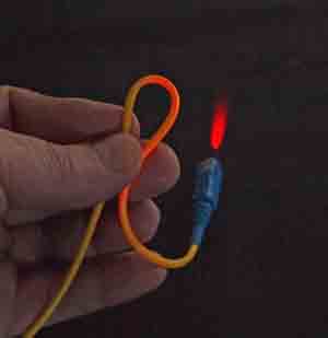
Connect a cable to the VFL or visual tracer, and
check continuity by seeing if the fiber transmits
light. Compare the amount of light transmitted
through SM and MM fiber.
While the cable is connected to the VFL, put bends
in the fiber as shown above (yellow jacket SM fiber
shown) and note the loss in the cable. Can you tell
a difference in the output of the fiber at the
connector? Why?
If you have a cable (preferably
yellow jacket SM fiber) you are willing to
damage, break the fiber and see what the
cable looks like.
Visual Inspection
With A Microscope
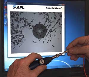
Tools
and equipment needed
Fiber
optic inspection microscope, either
optical or video (shown)
Fiber
optic cleaning supplies
Patchcords
and cables, both SM and MM
YouTube
Video: Visual
Inspection of
Connectors With A
Microscope,
FOA
Lecture 13: Testing
Fiber Visually
Online
Guide: Microscope
Inspection of
Connectors
Inspect the connectors on the patchcords
or cables with the microscope immediately
upon removal of the dust caps. What do you
see?
Clean the connectors and inspect again. Is
the ferrule surface clean? If not clean
again. Use both wet and dry methods.
Replace the dust cap, remove it and check
the connector again. Was it still clean?
Touch the end of the connector with your
finger and inspect it. Clean and inspect
again.
Drop a connector on a carpet (perhaps the
one on the cable you broke for the VFL
exercise) and inspect
it. Clean and inspect
again.
Measuring Optical
Power
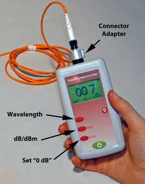
Tools
and equipment needed
Fiber
optic light source and power meter,
adapters for connectors used on patchcords
and cables
Fiber
optic cleaning supplies
Patchcords
and cables, both SM and MM
YouTube
Videos: FOA
Lecture 14: Testing Optical Power
Online
Guide:
Measuring
Optical Power,
Units of
Measure (dB, dBm),
Calibration and
Uncertainty in Fiber Optic Power Measurements
Turn on the source and let the output stabilize.
Turn on the meter and familiarize yourself with the
controls. Put the meter on dBm and set the
wavelength to the wavelength of your source.
Measure the power output of the light source. Stress
the cable by putting bends in it (as with the VFL
exercise) and note the differences. Change the
wavelength setting to another wavelength and note
the changes. Why does the measured power change?
Measure the output of a 850nm or 1300nm LED source
with both SM and MM fiber? What changes do you note?
Loss Budget
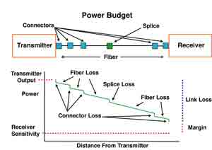
YouTube
Videos:
FOA
Lecture 26, Loss Budgets
Online
Guide:
What
Loss Should You Expect?,
Link
Loss Budgets And Power Budgets
Before measuring loss, it is important to calculate
a loss budget so you have an idea of what the loss
should be if the components are in good condition.
A: Calculate the loss budget for a long distance
network: singlemode fiber, 75km long, 14 splices, LC
connectors on each end. Fiber attenuation at 1550nm
is 0.21 dB/km, splices average 0.05dB and connector
losses are 0.3dB/km.
B:
Calculate the loss budget for a metropolitan
network: singlemode
fiber, 6.5km
long, 2 splices, one intermediate patch
panel plus LC connectors on each end. Fiber
attenuation at 1310nm is 0.40 dB/km, splices
average 0.05dB and connector losses are
0.3dB/km.
C:
Calculate the loss budget
for a LAN backbone: OM3
fiber 210meters long, no
splices, two intermediate
patch panels plus SC
connectors on each end.
Fiber attenuation at 850nm
is 3.10 dB/km and connector
losses are 0.5dB/km.
Answers
below.
How to calculate loss
budgets easily: FOA
has a free loss budget
calculator for iPhones and
iPads.
Calculate loss budgets for a cable plant you can
make from the cables you have for the exercises.
Remember you need two patchcords for reference test
cables.
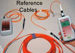
Single Ended Loss
Test
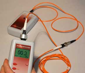
Tools
and equipment needed
Fiber
optic light source and power meter,
adapters for connectors used on patchcords
and cables
Fiber
optic cleaning supplies
Patchcords
and cables, both SM and MM, at least
three of the same type for testing (2
reference test cables and one cable to
test) and mating adapters
YouTube
Videos:
FOA
Lecture 16: Insertion Loss
Testing ,
Online
Guide:
Installed
Cable Plant
Testing (FOA-1,
OFSTP-7 & 14),
FOA
Standard FOA-1,
What
Loss Should You
Expect?,
VHO:
Insertion
Loss
If
you are not familiar with the operation of
these instruments read the manuals and work
with the instrument until you know how to
change test parameters and interpret the
display.
Attach one cable
to the source which will be the reference "launch
cable" and measure the output with the power meter.
Set the power meter on the 'dB" range and push the
button to zero the reading, setting the "0dB"
reference.
Using a mating adapter, attach a second cable (the
cable to test) to the launch cable and measure the
loss. What are your measuring?
Reverse the cable to test and measure again. Is the
loss different? Why?
Test other cables and record the results.
Modify
the launch conditions with a mandrel wrap on
the launch cable. Make a measurement of a
cable under test and record the results.
Wrap 5 turns of the cable around a 25mm (1
inch) mandrel (any round object will work)
and repeat the test (set 0dB reference,
check connection to receive cable, insert
cable to test and record data.) Are the
results different? Why? Repeat the test with
a cable plant made from several cables and
note the results.
Use a 62.5/125 micron cable for a launch
cable and test a 50/125 cable. What is the
result? Use a mandrel wrap on the launch
cable and repeat the test. What is the
result? Use the same 62.5/125
micron cable launch cable to
test a WM cable. What is the
result?
Use
a 50/125 micron cable for a launch
cable and test a 62.5/125 cable.
What is the result?
Double Ended
Loss Test
Tools
and equipment
needed
Fiber
optic light source and power meter,
adapters for connectors used on patchcords
and cables
Fiber
optic cleaning supplies
Patchcords
and cables, both SM and MM, at least
three of the same type for testing (2
reference test cables and one cable to
test) and mating adapters. The cable to
test for the exercises should be long
enough to also be used in the OTDR test
exercise as you will compare the test
data for each method.
YouTube
Videos:
FOA
Lecture 16:
Insertion Loss
Testing ,
Online
Guide:
Installed
Cable Plant
Testing
(FOA-1,
OFSTP-7 &
14),
FOA
Standard FOA-1,
What
Loss Should
You Expect?,
VHO: Insertion
Loss.
Insertion
Loss Simulator allows you to use
a virtual source and power meter to test a
cable plant, step-by-step.
Use it with your source and meter to test insertion loss
or do the test virtually using the simulator. Both
singlemode and multimode versions are available and you
see how Loss Budgets are used in testing.
Testing cable with the insertion loss simulator
If
you are not familiar with the
operation of these instruments read
the manuals and work with the
instrument until you know how to
change test parameters and interpret
the display.
Attach
one cable to the source which will be the reference
"launch cable" and measure the output with the power
meter. Set the power meter on the 'dB" range and
push the button to zero the reading, setting the
"0dB" reference.
Using a mating adapter, attach a second cable (the
cable that will become the receive cable) to the
launch cable and measure the loss. What are your
measuring? DO NOT RESET the "0dB"
reference.
Detach the two cables and insert a cable to
test using another mating adapter and
measure the loss. What are your
measuring?
Reverse the cable to test and measure again. Is the
loss different? Why?
Change
the reference method to a "two cable
reference," i.e. set the zero dB reference
with both a launch and receive cable and
repeat the test on the same cable you just
tested. Record the results. What is
different and why?
Change
the reference method to a "three
cable reference," i.e. set the zero
dB reference with both a launch and
receive cable and a third reference
cable between them and repeat the
test on the same cable you just
tested. Record the results. What is
different and why?
Compare your tests of the same cable
with one, two and three cable
reference methods.
Test other cables and record the results.
Modify the launch conditions with a mandrel wrap on
the launch cable. Make a measurement of a cable
under test and record the results. Wrap 5 turns of
the cable around a 25mm (1 inch) mandrel (any round
object will work) and repeat the test (set 0dB
reference, check connection to receive cable, insert
cable to test and record data.) Are the results
different? Why? Repeat the test with a cable plant
made from several cables and note the results.
Use a 62.5/125 micron cable for the launch and
receive cable and test a 50/125 cable. What is the
result? Why?
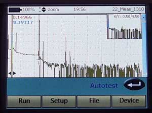
OTDR
Testing
Tools
and equipment
needed
OTDR
with adequately long launch and receive
reference test cables, preferably of the
same fiber and equal lengths.
Fiber
optic cleaning supplies
Cables
of sufficient length to test with an
OTDR, both SM and MM if the OTDR tests
both, and mating adapters
(Optional - use the FOA OTDR
Simulator or Fiberizer
to simulate the test if you do not have
an OTDR or adequate fiber to test.)
YouTube
Videos: FOA
Lecture 17: OTDR Testing,
FOA
Lecture 18: OTDR Setup,
FOA
Lecture 19: OTDR Measurement
Uncertainty
Using
An OTDR (Hands-On)
Online
Guide:
OTDR
testing ,
Frequently
Asked Questions about OTDRs
VHO:
OTDR.
Software
Download: OTDR
Simulator
With
an OTDR
If you are not familiar with the operation of this
OTDR read the instrument manual and operate the
instrument until you know how to set parameters
manually, take traces and analyze them using both
"two-point" and "LSA" methods.
Connect a launch cable to the OTDR and set the OTDR
in the manual mode. Choose a range appropriate for
the launch cable, typically the shortest range for
the OTDR. Set the pulse width to the shortest option
and averaging to a short time period or ~32-64
cycles. Set the wavelength to 850nm for MM or 1310nm
for SM. Take a trace of the launch cable. Measure
how long it takes for the trace to return to the
baseline (the "dead zone"). Change the pulse width
to longer options and measure the changes to the
length of the dead zone.
Attach a cable to test to the launch cable and reset
the OTDR to the shortest pulse. Take a trace. Can
you see the end of the fiber in the cable under test
or is it too noisy? If it is too noisy, go to a
longer OTDR pulse or average for a longer time until
you an clearly see the end of the cable under test.
Using the two marker method, measure the loss of the
connection between the launch cable and the cable
under test and the
attenuation of the fiber in the cable under
test. Record the
results (including saving the traces for later
comparison.) Repeat the tests using the LSA methods.
Record the results and compare to the two marker
method. Are there differences? Why? Measure the
reflectance of the connection between the launch
cable and cable under test. Can you measure the loss
of the connector on the far end of the cable under
test? If not, why not? Change the OTDR to the
"autotest" mode and repeat the measurement. Compare
the results. What is different?
Do you see any "ghosts" in the traces?
Attach a receive cable to the far end of the cable
under test. Now using the two marker method, measure
the loss of the connections on either end, the
attenuation of the fiber in the cable under test and
the total loss of the cable under test including the
connections on each end. Record this data for
comparison.
Repeat
the tests using the LSA methods. Record the results
and compare to the two marker method. Are there
differences? Why?
Reverse the cables
(remove the launch cable from the OTDR and connect
the OTDR to the open end of the receive cable
without disturbing the other connections) and repeat
the tests. Record
the results and compare to the two marker
method. Are there differences? Why? Change
the OTDR to the "autotest" mode and
repeat the measurement. Compare the
results. What is different?
Record the
traces at one wavelength and test at the
other (e.g if you have MM traces at 850nm,
take a new trace at 1300nm, or SM at 1310nm,
change to 1550nm.) Compare the traces. Is
the fiber attenuation different? How about
connections?
With The
OTDR Simulator
Install the OTDR simulator on your PC. Open
the program (ignore the warning that it is
looking for the hardware of the PC OTDR it
was written for.) Follow the manual to
understand how the OTDR Simulator works.
Go to the folder "Parameter Traces" and open
the traces w-850.sor and w-1300.sor and
compare them. Each set of files with the
same beginning to the name are meant to be
compared. Do that with each set to see what
happens when you change parameters on the
setup menu of the OTDR. The folders Traces
and Span Traces include more traces to
analyze.
Test
Your Comprehension - Online
Quiz On Testing
Have
you completed the Workbook worksheets that are the
records of your having successfully completed the
exercises?

Get a "Certificate
of Completion" When You Complete The Course
After you complete all six lessons of the Fiber U Basic Skills Lab
Fiber Optics online self-study course, you can
now take an online exam and, when you pass the
exam, get a "Certificate of Completion" for this
course. You should complete all lessons
including taking the quiz ("Test Your
Comprehension") at the end of every lesson. When
you think you are prepared, you can take an
online exam for a nominal fee ($20) which will
give you a "Certificate of Completion" for
this course.
Take the Test to Get Your
Certificate of Completion For This
Course
Loss Budget Answers:
A: Calculate
the loss budget for a long distance network:
singlemode fiber, 75km long, 14 splices, LC
connectors on each end. Fiber attenuation at
1550nm is 0.21 dB/km, splices average 0.05dB and
connector losses are 0.3dB/km.
Loss = 75km x 0.21dB/km (=15.75dB) + 14 splices x
0.05dB (=0.70dB) + 2 connections X 0.30dB
(=0.60dB) = 17.05dB
B:
Calculate
the loss budget for a metropolitan
network: singlemode
fiber, 6.5km
long, 2 splices, one intermediate patch
panel plus LC connectors on each end.
Fiber attenuation at 1310nm is 0.40 dB/km,
splices average 0.05dB and connector
losses are 0.3dB/km.
Loss
= 6.5km x 0.40dB/km (=2.60dB) +
2 splices x 0.05dB (=0.10dB) + 3
connections X 0.30dB (=0.90dB) =
3.60dB
C:
Calculate
the loss budget for a LAN
backbone: OM3 fiber
210meters long, no
splices, two intermediate
patch panels plus SC
connectors on each end.
Fiber attenuation at 850nm
is 3.10 dB/km and
connector losses are
0.50dB/km.
Loss
= 0.21km x 3.10dB/km (=0.65dB) +
4 connections X 0.50 dB
(=2.00dB) = 2.65dB
Return
to Fiber U Basic Skills Lab Lesson Plan
|