Lesson:
Building and Testing A Fiber Optic Link - Part 1 - Duplex Link
Objectives:
From this lesson you should learn:
How to build a fiber optic link using media converters
Testing the fiber optic link
Using transmitter sources to test the fiber optic link
cable plant
Components
Safety Glasses
Visual Fault Locator (VFL) or the VFL in the power meter
if it has one
Fiber optic
cable
Fiber Optic Media Converters
Media converters are special fiber optic transceivers used to
convert from one type of cable (the media) to another, typically from
copper cables to fiber optics, although some media converters will
convert from one fiber type to another, e.g. multimode to singlemode.
The FOA Guide has a page about media converters you should read before beginning this exercise.
We have exercises for two types of media converters. Exercise 1 uses media converters that connect over two fibers like the majority of fiber optic links. Exercise 2 uses media converters
that connect over one fiber while still providing full-duplex
(simultaneous) communications bidirectionally over the one fiber. The
one fiber bidirectional links are similar to those used in passive
optical networks (PONs) used in FTTH (fiber to the home) and optical
LANs, so Exercise 2 includes an option to build a PON demonstration.
Both types of media converters are available for purchase online at very
reasonable prices. The exercises show how to use media converters that
use Ethernet protocols to allow connecting computers to the Internet.
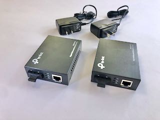
Typical media converters
2
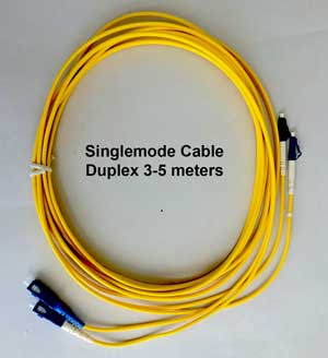
singlemode fiber
media converters- you will be using singlemode
fiber
cables from the installation exercises to connect
them. If you plan to do both exercises, you will need 2 sets of media
converters, one set that operates over two fibers and one set that
operates over a single fiber bidirectionally.
You will
connect them over 2 or 4 fiber optic cables used in the other exercises
Also
you need two
Cat 5e patchcords to connect your computer and
router to the media converters. Purchase these online if you do not have
any.
PON Splitter
If you wish to do the PON demo in exercise 2, you will need a PON splitter. Order a "1 X 4" or 4 port splitter online.
Fiber Optic Power Meter
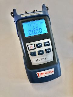
This fiber optic power meter measures in dBm and W and
has a dB range for loss measurements.
It has adapters for SC connectors and any connector with
2.5mm ferrules.
Connecting With The Link You Build
To connect with the link, you need an Ethernet
connection to the Internet and a device that can connect
to the Internet over Ethernet on UTP Cat 5 cable..
Your Internet connection should have a router with
Ethernet ports which can be used.
If you have a computer with an Ethernet port, that will be
ideal for completing the link. You can also use a WiFi
access point connected to your router over UTP Cat 5e
cable for the exercise.
Safety:
 |
Always
wear safety glasses when doing any of
these exercises and dispose of all fiber
scraps properly.
Safety
Rules - Read before beginning any
exercises.
Do
not look directly into the light from the
visual fault locator - it's bright!
|
Exercise
Before you start, review the use of fiber optic media
converters from the FOA
YouTube video on media converters, the
FOA Guide page on media converters or the Fiber
U MiniCourse on media converters.
Watch the FOA YouTube Video Of This DIY Link Demo Exercise
Check Your Cables
1: Attach
your cables to the Visual Fault Locator (VFL)
2. Turn the VFL on and ensure the light travels through
the fiber. You can see how bright the glow is at the end
of the fiber, diffused through the fiber protective cap.
This shows how fiber transmits light by total internal
reflection as you learned in the lesson on optical fiber.
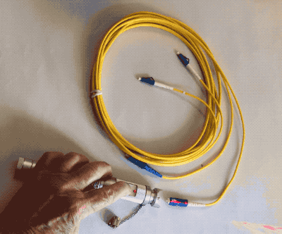
Repeat for all the cable you are using in this exercise.
Exercise 1
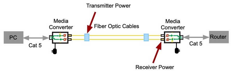
Build A Fiber Optic Link
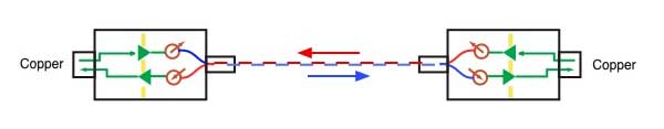
Exercise 1 uses media converters that connect over two fibers like the majority of fiber optic links.
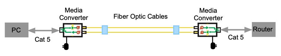
This link uses two media converters that convert Ethernet
on Cat 5 to fiber optics. The diagram above is the link we
will build.
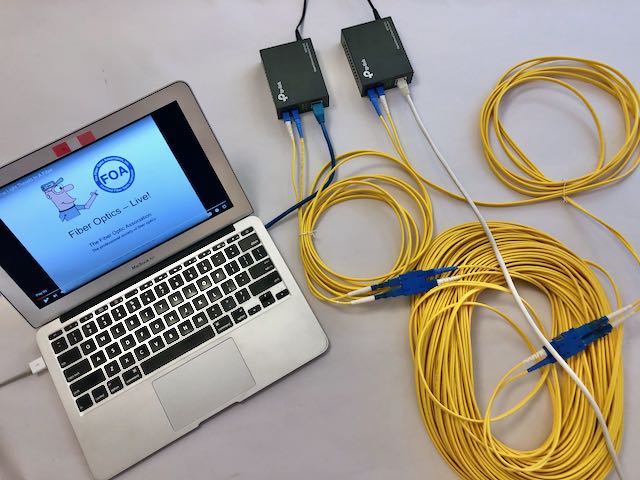
1. Assemble the equipment you need.
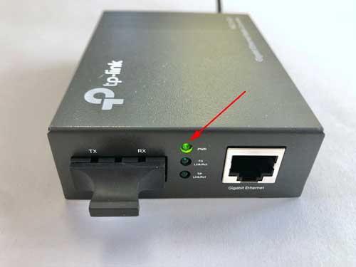
2. Power up the media converters and confirm the power
light.
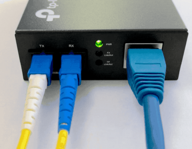
3. Connect
the two media converters with duplex cables, preferably 3
cables connected with mating adapters. Did your link show
the link connection light? If not did you remember that
the fibers must be crossed to connect the transmitter
output of one to the receiver input of the other.
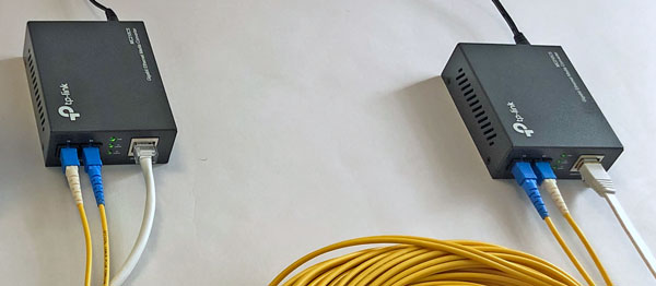
Note how blue and white connectors are reversed to make
transmitter to receiver connections. You should now have
the middle indicator light on, showing the fiber link is
working.
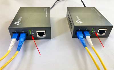
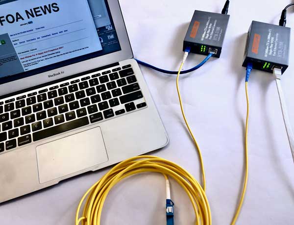
4. Connect your Ethernet devices to the link with UTP Cat
5e cables and confirm the link transmits data. You can
check the indicator lights to ensure the bottom light is
flashing which shows data is being transmitted.
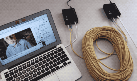
Here is our link transmitting data, connecting our laptop
to the Internet over fiber optics.
Here we're watching a FOA
YouTube video on cleaning fiber optic connectors.
The Ethernet fiber optic link you have built is
essentially the same as every digital fiber optic link.
Test Your Fiber Optic Link
Next we will test the link we have built. We want to
test transmitter power, receiver power and use them to
determine the loss of the cable plant we are using.
If we know the output of the transmitter, we can set
that as our "0dB" reference and when we measure the
receiver power, it will be lower by the loss of the cable
plant. This is just like making an insertion loss test
except we are using the transmitter as our test source.
Turn on your power meter and set the range to dBM to
measure the power. Disconnect the patch cord connecting
the transmitter of one of the media converters and plug it
into the power meter.
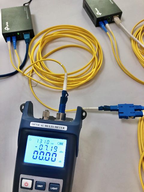
The output of this transmitter is -7.19dBm (middle
display) so we can confirm the transmitter source is
operating and we have set this to be our "0dB" reference
for testing the cable plant. Reconnect this patchcord to
our cables.
Next disconnect the receiver input of the other media
converter and plug that into the meter.
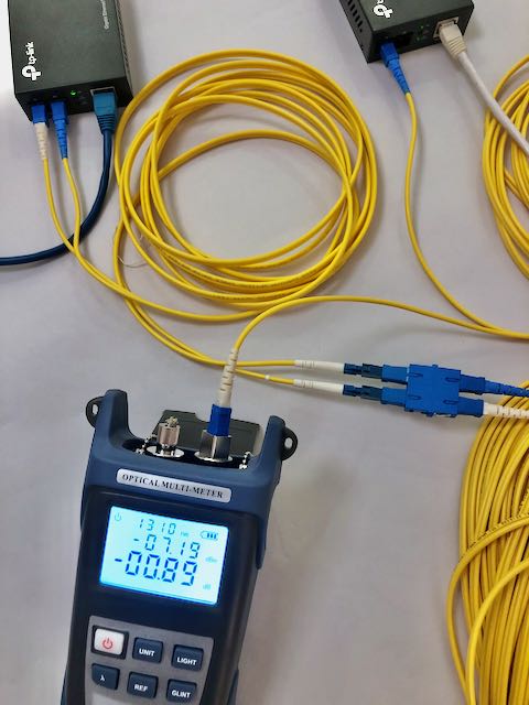
The meter is still set to read dB on the lower scale and
the loss of the cable plant is 0.89dB. The middle display
still shows the transmitter output which we used for a 0dB
reference.
We can also measure the input power of the receiver of
this module by switching the display to dB/W.
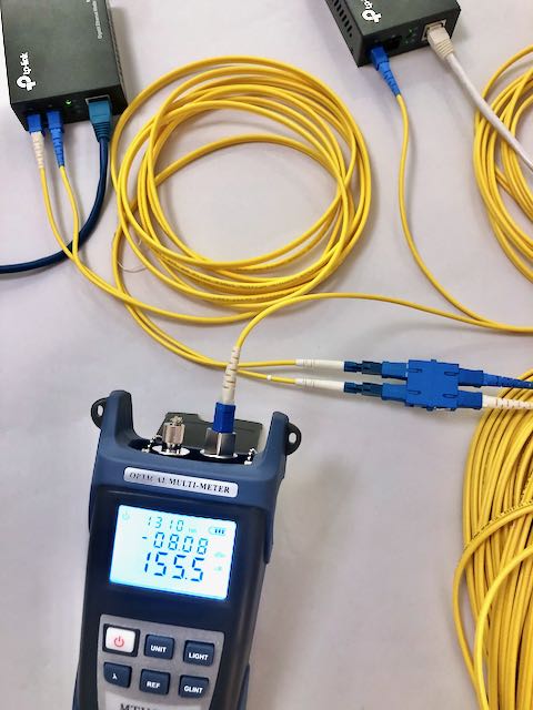
The input to the receiver of this media converter is -8.00
dBm or 155.5nW ().156mW).
Our exercise showed how to test the transmitter power and
receiver power and how to use the transmitter as a test
source to measure the loss of the cable plant.
You
have successfully completed this exercise
when you have built a fiber optic link using
the media converters and used it to transmit
data. You also should have tested the power
in the link at the transmitter and receiver
and use the transmitter to test the cable
plant.
Complete the exercise and fill in your Scorecard.
Exercise 2
Build A Bidirectional Fiber Optic Link And A Passive Optical Network (PON)
Return
to Lesson Plan
This information is
provided by The Fiber Optic Association, Inc. as a
benefit to those interested in teaching, designing,
manufacturing, selling, installing or using fiber optic
communications systems or networks. It is intended to be
used as an overview and/or basic guidelines and in no
way should be considered to be complete or
comprehensive. These guidelines are strictly the opinion
of the FOA and the reader is expected to use them as a
basis for learning, as a reference and for creating
their own documentation, project specifications, etc.
Those working with fiber optics in the classroom,
laboratory or field should follow all safety rules
carefully. The FOA assumes no liability for the use of
any of this material.
|